Everything you need to build your own: parts, steps, and wiring.
The build uses a Raspberry Pi 4B, addressable LED strips, plywood, CLS timber, and 3D-printed parts. The print files and Python code are on GitHub. Our electronics were fully enclosed and PAT tested.
Electronics parts list
The main electronics for the whole build. Each stage below lists what it needs, including the smaller components.
Item
Quantity
Raspberry Pi Model 4B (and power supply)
×1
Female Barrel Jack
×4
Male Barrel Jack
×3
Arcade Buttons
×2
1 meter LED strip x4 (60 LEDs per meter; addressable)
×1
5V 10A Power supply with male barrel jack connector (for LEDs)
×1
12V 2.5A Step Up/Step Down Voltage Regulator
×1
1000 µF capacitor
×1
Monitor with HDMI input (and power supply)
×1
Stranded wire for connections
lots
1. Tower Support Box
You will need
Part
Quantity
Size
Material
Tower Support Platform
×1
410 mm × 410 mm
9 mm plywood
Tower Support Front Panel
×1
410 mm × 145 mm
5 mm plywood
Tower Support Back Panel
×1
410 mm × 145 mm
5 mm plywood
Tower Support Side Panel
×2
410 mm × 145 mm
5 mm plywood
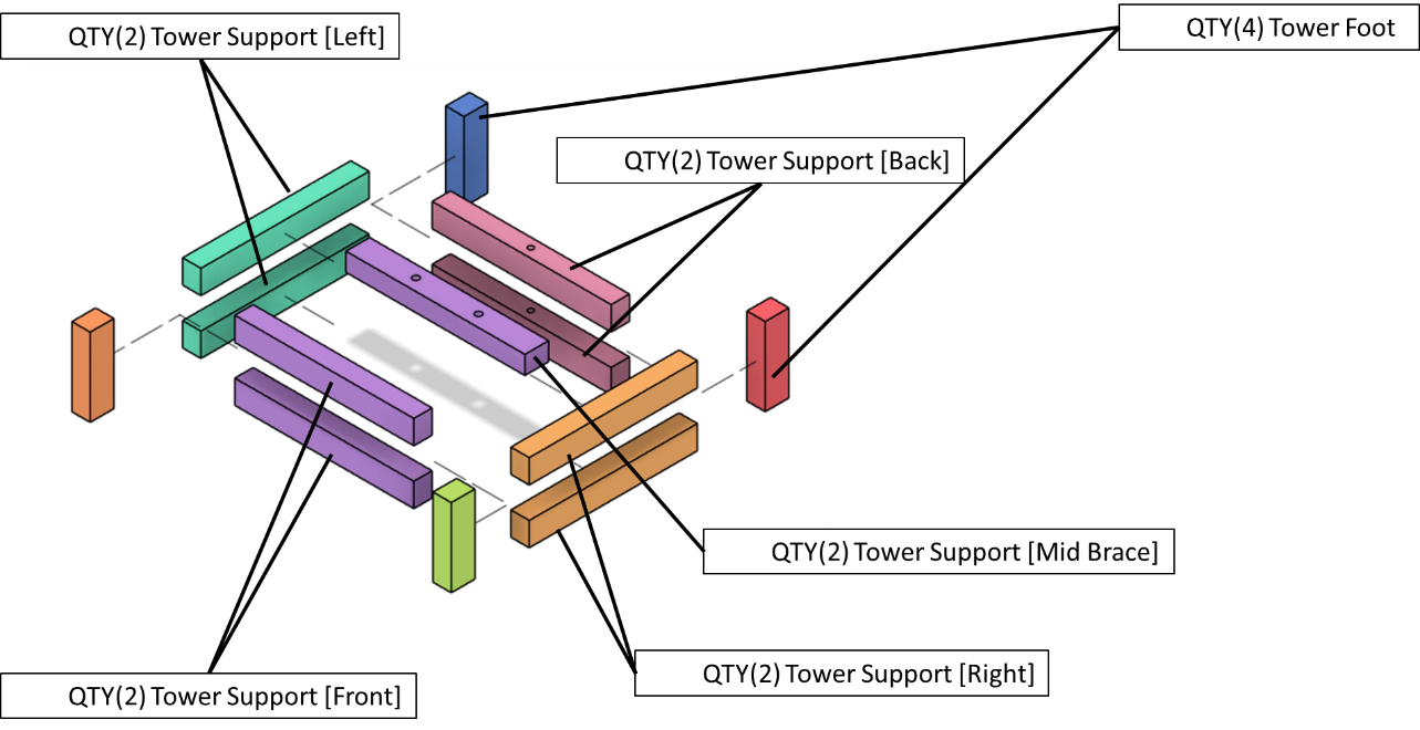
Tower Foot
×4
145 mm length
44 mm × 34 mm CLS lumber
Tower Support (Left)
×2
312 mm length
44 mm × 34 mm CLS lumber
Tower Support (Right)
×2
312 mm length
44 mm × 34 mm CLS lumber
Tower Support (Front)
×2
332 mm length
44 mm × 34 mm CLS lumber
Tower Support (Back)
×2
332 mm length
44 mm × 34 mm CLS lumber
Tower Support (Mid Brace)
×2
332 mm length
44 mm × 34 mm CLS lumber
M10 Bolts
×3
M10, 120 mm
-
Woodscrews
×18
4 mm × 70 mm
-
Woodscrews
×31
4 mm × 15 mm
-
Steps
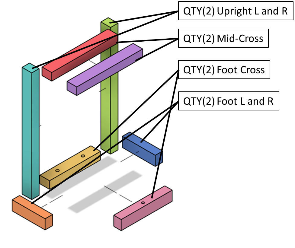
Cut all CLS pieces to size.
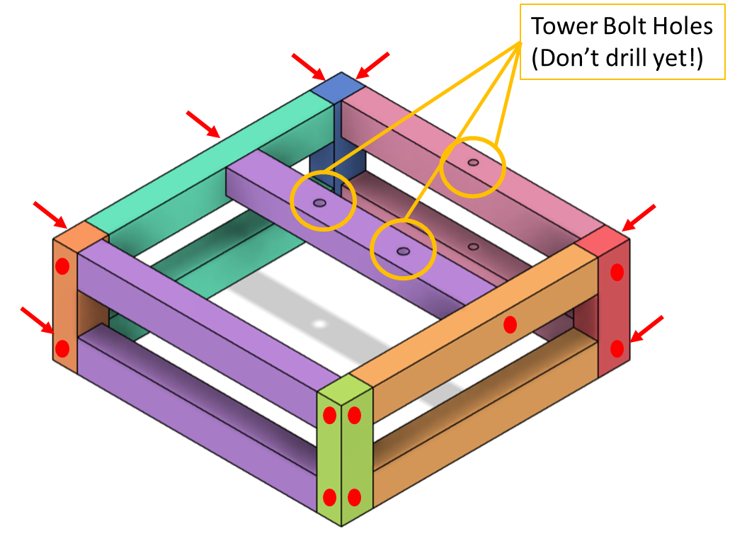
Do NOT pre-drill holes in the Mid Brace of Tower Support (Back) yet. These need to be drilled with the tower so everything lines up.
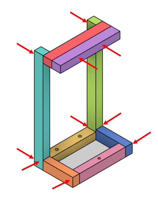
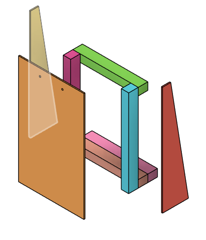
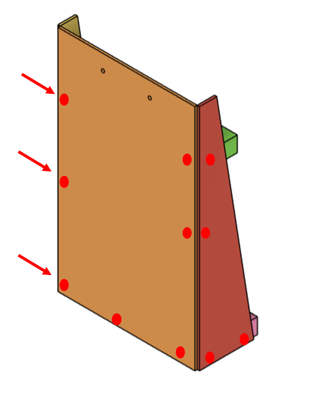
Screw the Tower Support CLS sections together at the red marked locations on each Tower Foot with 4 mm × 70 mm woodscrews. Use clamps to help keep things square. (Figures 1-2)
Figure 1: Tower Support Frame.Figure 2: Tower Support Frame Screw Locations.
Cut all plywood sheets to size.
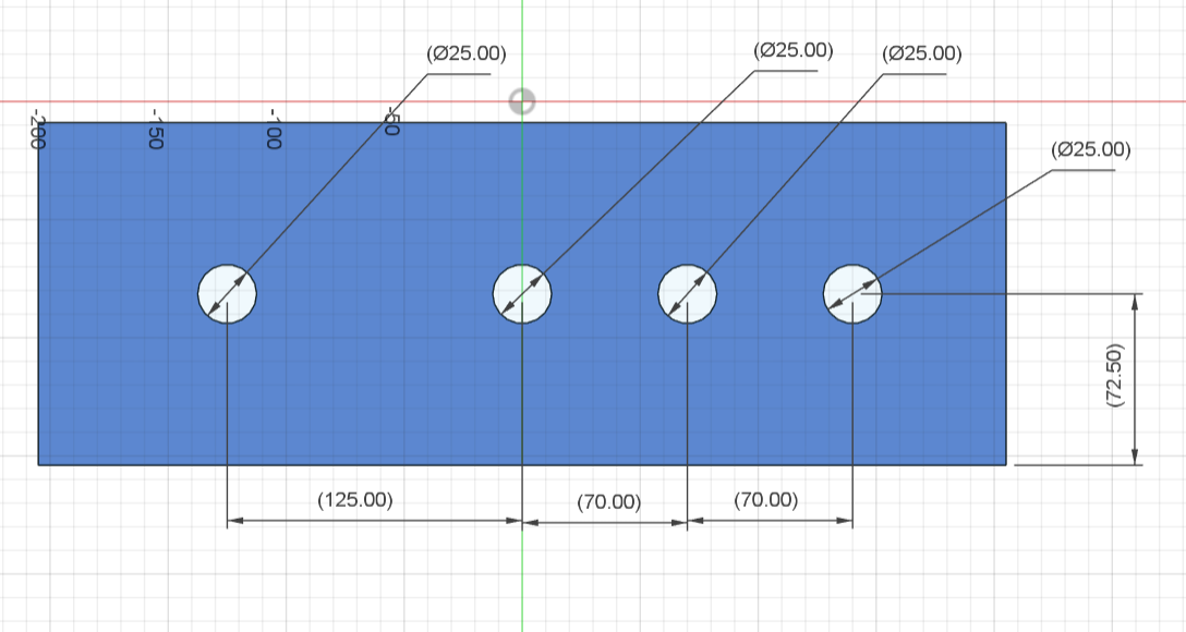
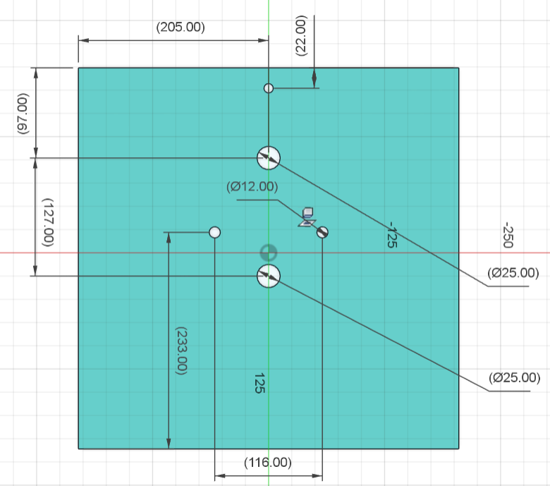
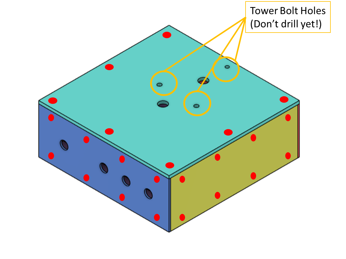
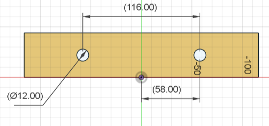
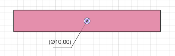
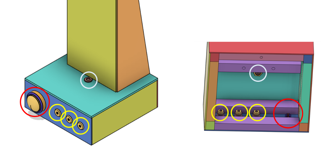
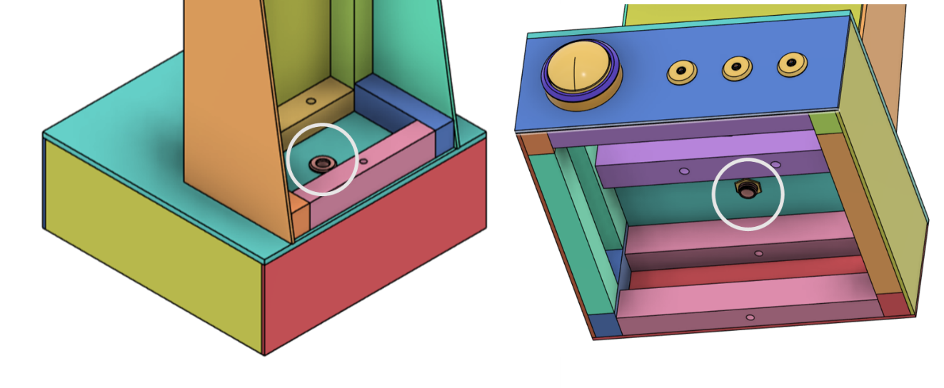
Pre-drill the electronics holes in the Support Platform and Front Panel, but NOT the Tower Bolt Holes in the Support Platform. These need to be drilled with the tower so everything lines up (Figures 3-4).
Figure 3: Tower Bottom Front Panel Holes.Figure 4: Tower Bottom Platform Holes.
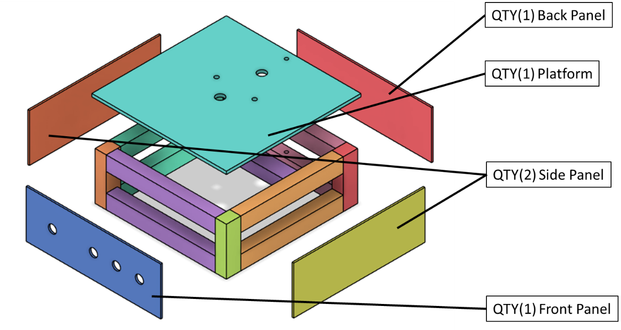
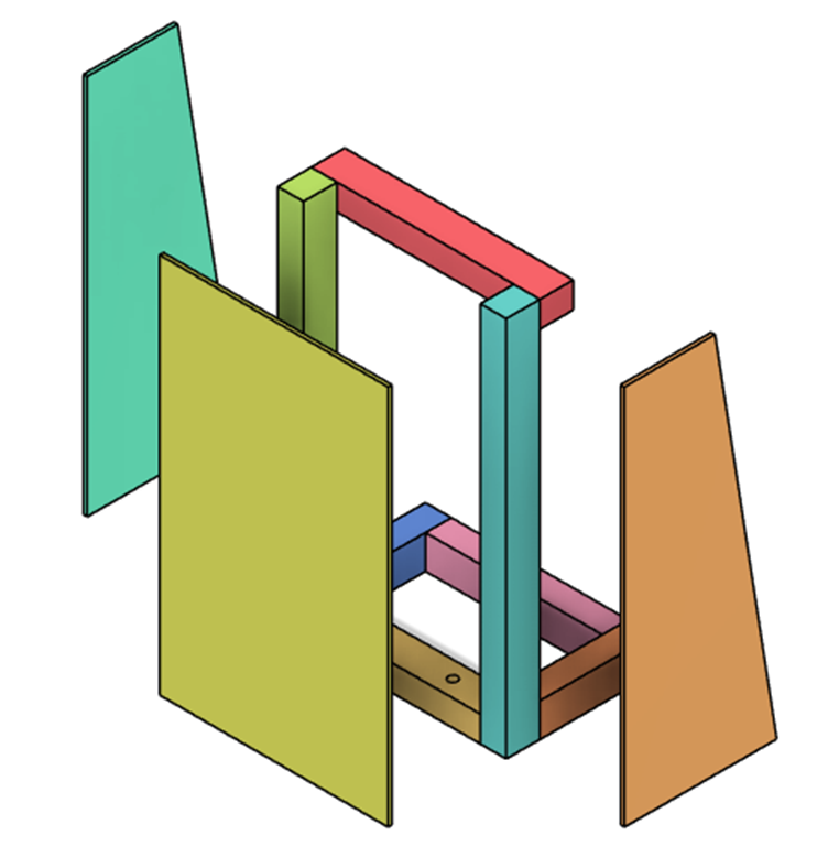
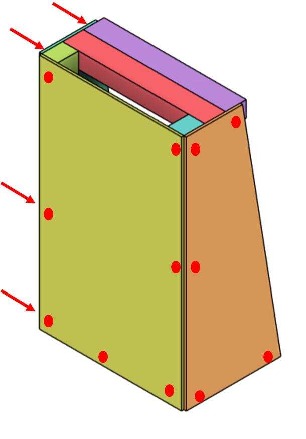
Use 4 mm × 15 mm woodscrews to attach all the panels to the Tower Support frame, at the red marked locations, on all the panels. Make sure to avoid the existing screws in the frame Tower Feet just to the inside of the Frame screws (Figures 5-6).
Figure 5: Tower Support Panels.Figure 6: Tower Support Panel Screw Locations.
Lightly sand down any sharp edges.
Paint the outside of the Tower Support Box.
2. Tower Bottom
You will need
Part
Quantity
Size
Material
Tower Bottom Front Panel
×1
500 mm × 310 mm
5 mm plywood
Tower Bottom Side Panel (Left and Right)
×2
500 mm × 200 mm
5 mm plywood
Tower Bottom (Left and Right Upright)
×2
500 mm length
44 mm × 34 mm CLS lumber
Tower Bottom Foot Cross
×2
232 mm length
44 mm × 34 mm CLS lumber
Tower Bottom Foot (Left and Right)
×2
150 mm length
44 mm × 34 mm CLS lumber
Tower Bottom Mid-Cross
×2
300 mm length
44 mm × 34 mm CLS lumber
Woodscrews
×10
4 mm × 70 mm
-
Woodscrews
×17
4 mm × 15 mm
-
Steps
Cut all CLS pieces to size.
Using the 3D Printed Drill Guide Pre-drill the 10 or 12 mm diameter holes in the Foot Crosses (Figures 7-8).
Figure 7: Tower Bottom Front Foot Cross Holes.Figure 8: Tower Bottom Back Foot Cross Holes.
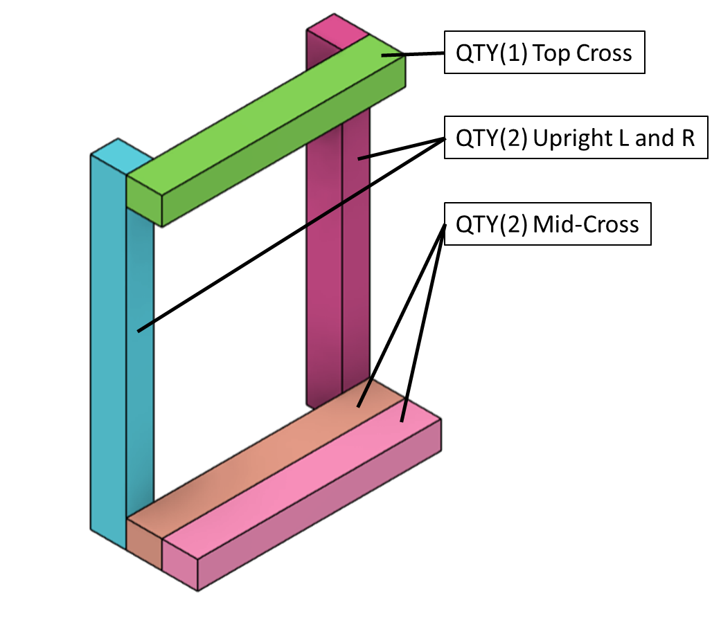
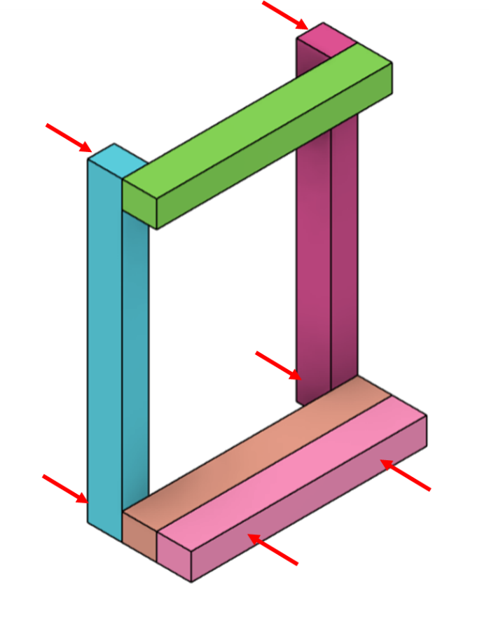
Using 4 mm × 70 mm screws, attach the Tower Bottom frame pieces together (Figures 9-10).
Figure 9: Tower Bottom Frame.Figure 10: Tower Bottom Frame Screw Locations.
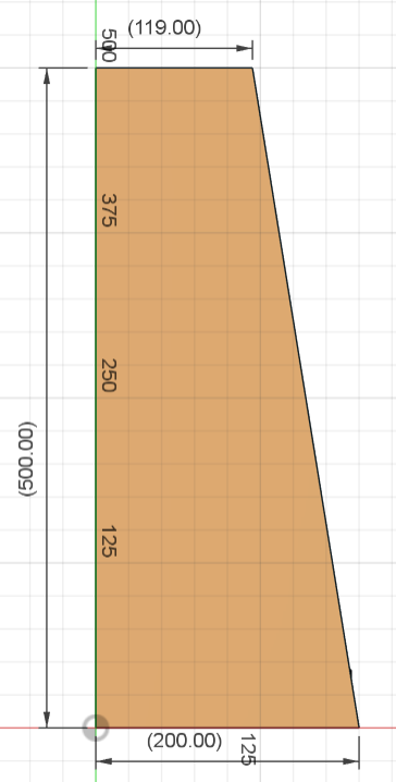
Cut all Plywood sheets to size. Cut the Side panels at an angle as in the diagram in Figure 11.
Figure 11: Tower Bottom Side Panel Dimensions.
Using 4 mm × 15 mm woodscrews, attach the Front and Side Panels (Figures 12-13).
Figure 12: Tower Bottom Panels.Figure 13: Tower Bottom Panel Screw Locations.
Lightly sand down any sharp edges and paint the outside of the Tower Bottom.
3. Tower Top
You will need
Part
Quantity
Size
Material
Tower Top Front Panel
×1
500 mm × 310 mm
5 mm plywood
Tower Top Side Panel (Right and Left)
×2
500 mm × 119 mm
5 mm plywood
Tower Top Upright (Left and Right)
×2
400 mm length
44 mm × 34 mm CLS lumber
Tower Top Cross (Mid ×2, Top ×1)
×3
300 mm length
44 mm × 34 mm CLS lumber
Woodscrews
×6
4 mm × 70 mm
-
Woodscrews
×15
4 mm × 15 mm
-
Steps
Cut all CLS pieces to size.
Using 4 mm × 70 mm woodscrews, attach the Tower Top frame together (Figures 14-15).
Figure 14: Tower Top Frame.Figure 15: Tower Top Frame Screw Locations.
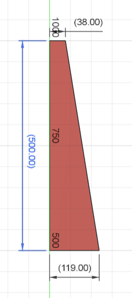
Cut all Plywood sheets to size. Cut the Side panels at an angle as in the diagram in Figure 16.
Figure 16: Tower Top Side Panel Dimensions.
Using 4 mm × 15 mm woodscrews, attach the Front and Side Panels (Figures 17-18).
Figure 17: Tower Top Panels.Figure 18: Tower Top Panel Screw Locations.
Lightly sand down any sharp edges and paint the outside of the Tower Top.
4. Tower Assembly
You will need
Item
Quantity
Subassemblies
Tower Top
×1
Tower Bottom
×1
Tower Support
×1
Hardware
Hinge and Mounting Screws
×1
Clips and Mounting Screws
×2
M10 × 120 mm Bolts
×3
M10 Washers
×3
M10 Nuts
×3
M4 × 16 mm Bolts
×4
M6 × 20 mm Bolts
×2
M6 Heat Set Inserts
×2
3D Printed Parts
Hook Screen Mounts (Left and Right)
×2
25 mm Hole Wire Grommets
×2
Barrel Jack Panel Mounts
×3
Electronics
Screen
×1
Arcade Button
×1
Tools
3D Printed M10 Drill Guide
×1
10 mm Drill Bit
×1
6 mm Drill Bit
×1
Drill
×1
Soldering Iron
×1
Steps
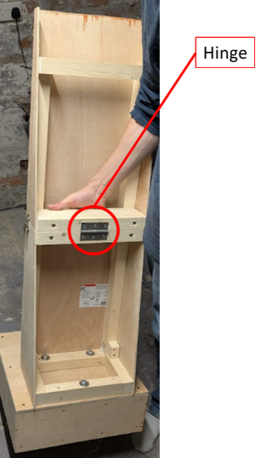
Attach the Tower Top to the Tower Bottom by aligning the Mid-Cross braces and Front Panels. Use the included mounting screws to attach the hinge in its open position (Figure 19).
Figure 19: Tower Hinge Location.
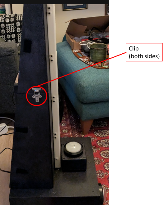
Attach the Clips to the Side Panels on the Tower Top and Tower Bottom, one half on each side of the tower sections, using the included mounting screws (Figure 20).
Figure 20: Tower Side Panel Clips Location.
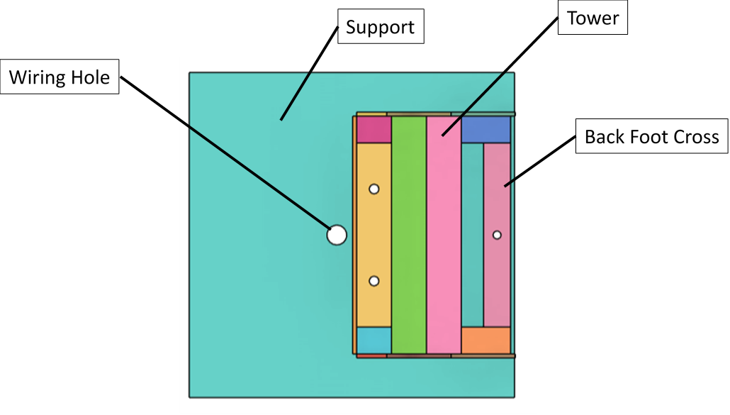
Align the Tower on the Tower Support centred Left to Right, the Front Panel of the tower just behind the hole in the centre of the Tower Support, and the Back Foot Cross of the tower at the back edge of the Support. Mark out the 10 mm drill holes (Figure 21).
Figure 21: Tower M10 Bolt Hole Locations.
Use the 3D Printed Drill Guide to drill through the Tower Support Platform panel and through the cross braces underneath.
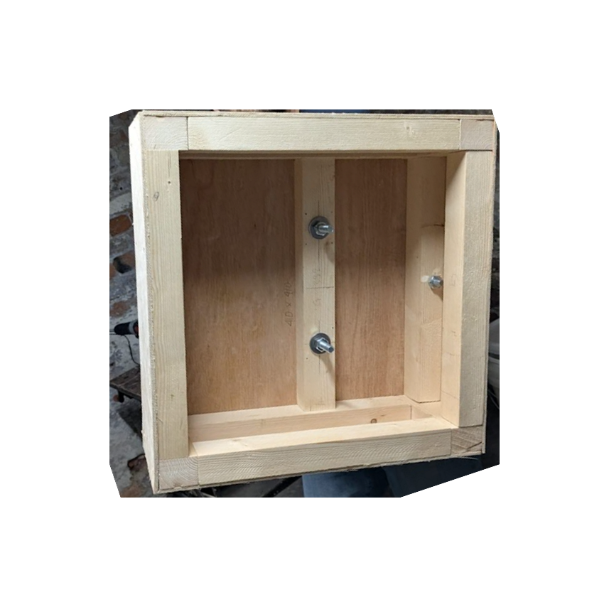
Use the M10 bolts, washers and nuts to attach the Tower to the Support base (Figure 22).
Figure 22: Tower Bolts Detail.
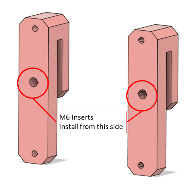
Use the Soldering Iron to press in M6 ×2 heat set inserts into the Screen Hook Mounts (Figure 23).
Figure 23: Screen Hook Heat Set Insert Locations.
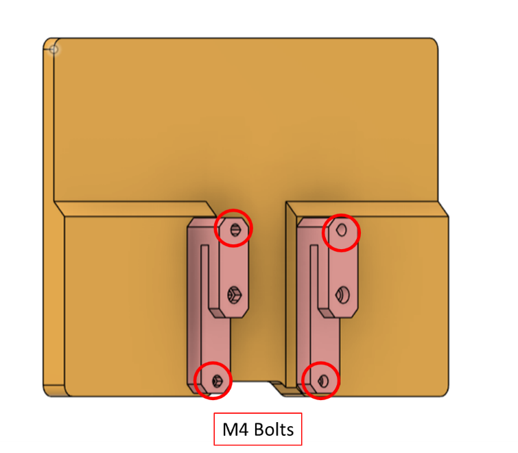
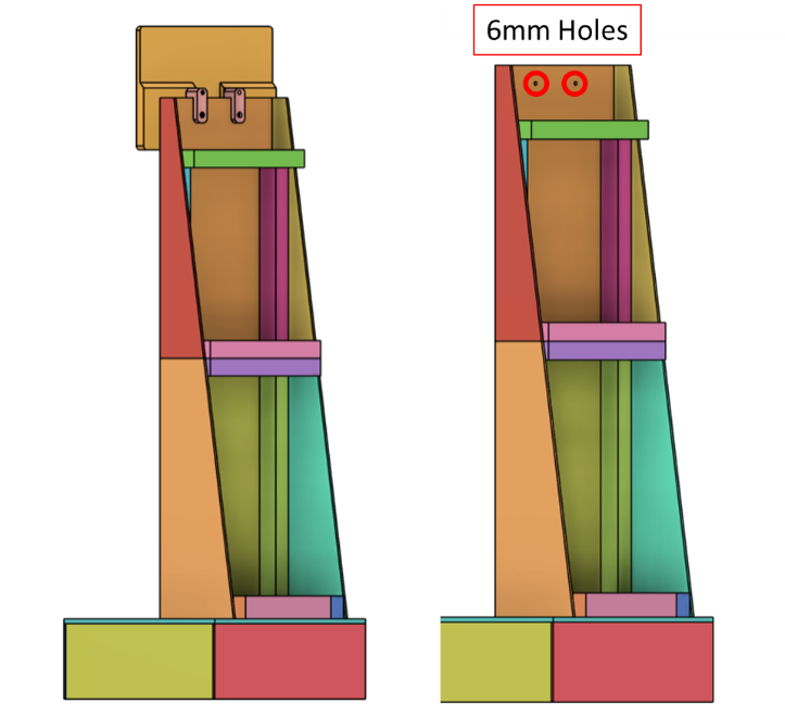
Attach the Screen Hook Mounts to the Monitor, hang the Monitor at the top of the tower and mark the holes to drill (Figure 24).
Figure 24: Screen Hook M4 Bolt Locations.
Remove and then drill the holes with the 6 mm drillbit (Figure 25).
Figure 25: Screen Mount Drill Hole Locations.
Paint the Barrel Jack Panel Mounts to match the Hammer Colours chosen.
Install the Select Arcade Button, Barrel Jack Panel Mounts, and Wire Grommets in the Support base by placing the front half through the holes from the outside, and using the associated plastic nuts to clamp the plywood from the inside of the Support base (Figures 26-27).
Figure 26: Front Panel Hardware Installation.Figure 27: Tower Wire Grommet Installation.
5. LED Assembly
You will need
Item
Quantity
3D Printed Parts
Diffuser Cover Top
×1
Diffuser Cover Bottom
×1
Diffuser Covers
×3
Diffuser Mounts
×5
Mount Glue Clamps
×5
Electronics
1 m Addressable LED Strips, 60 LEDs/m
×4
Male 3-wire JST Connector
×4
Female 3-wire JST Connector
×4
Hardware
M4 × 8 mm Bolts
×18
M4 Nuts
×18
Velcro Strips with Sticky Back
×1
Tools
Clamps
×1
Silicone Glue
×1
Steps
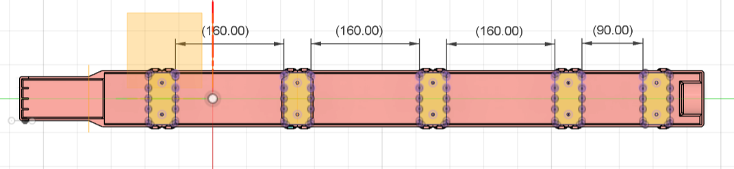
Cut LED strips into 1 m lengths (if needed). Solder the JST connectors between the sections, according to the wiring diagram.
Using the Mount Glue Clamp, take the Diffuser Mounts and place them according to the diagram in Figure 28, starting with the bottom of the LED strips at the right hand side of the diagram:
Figure 28: Diffuser Mount Clamp Orientation.
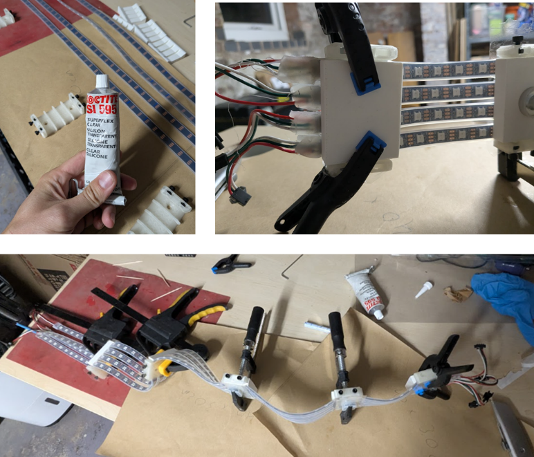
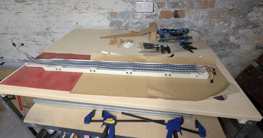
Use the Silicone Glue and Mount Glue Clamp to fix the strips to each Mount, and let them fully cure. Check the spacing against the LED Diffuser Covers, and adjust if needed (Figures 29-30).
Figure 29: Example of How to Glue and Clamp the Diffuser Covers.Figure 30: Completed Diffuser Cover Assembly.
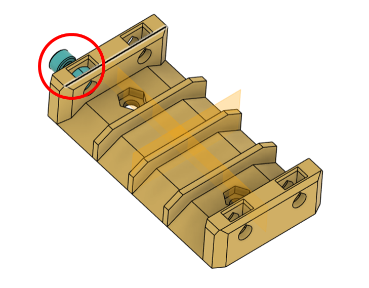
Place an M4 nut in each of the Diffuser Mounts, an M4 Bolt through the outer hole and screw it into the nut. Use a dab of Silicone glue to seal the slot and trap each nut (Figure 31). Let this cure fully.
Figure 31: M4 Placement in Diffuser Mounts.
Attach the Diffuser Covers onto the Mounts by unscrewing the M4 Bolts slightly, placing the pocket of the Diffuser plate over the bolt heads, then clamping the Diffuser Plates against the mount by tightening the bolts.
Place a strip of sticky-backed Velcro on each Diffuser Mount. Place the matching side onto the Velcro and remove the backing.
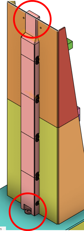
Stick the LED Assembly onto the Tower, hooking the Top Diffuser Cover on the Tower and lining up the Bottom Diffuser Cover around the Wire Grommet in the Tower Support. Take care the LED strips are in the channels of the Top Diffuser Cover so they don’t get pinched. Press firmly to stick the Velcro to the tower. (Figure 32)
Figure 32: Diffuser Cover Placement on Tower.
6. Hit Box and Hammers Assembly
You will need
Item
Quantity
3D Printed Parts
Hammer Button Box Top
×1
Hammer Button Box Bottom
×1
Hammer Button Box Body
×1
Hammer Caps
×6
Barrel Jack Hammer Plugs
×3
Electronics
Arcade Button
×1
3-strand Wire (1.5 m minimum)
×1
Single Stranded Wire (10 cm)
×1
Male Barrel Jack Hammer Plugs
×3
Hardware
M4 × 10 mm Bolts (or longer)
×8
Blade Terminals
×1
Hammers
×3
Thick String / Yarn (3 m minimum)
×1
Super Glue
×1
Tools
Wire Crimper for Blade Terminals
×1
Steps
Paint the Button Box parts, if desired.
Place ‘Hit’ Arcade button through the Button Box Top, and screw plastic nut on back to clamp it to the Top.
Cut the length of 3-strand wire needed to have the Button Box placed where you like (at least 1.5 m). Strip and terminate the 3 wire ends with blade terminals, and attach these to the button according to the wiring diagram.
Screw the Top to the Body with M4 bolts.
Make sure the wire lines up in the hole of the Box Body so it doesn’t get pinched, and screw the Bottom to the Body with M4 bolts.
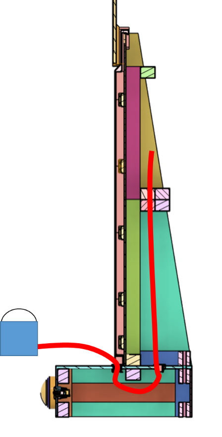
Run the 3-strand wire from the Wire Hole Grommet beneath the LED Diffuser and up through the Grommet inside the Tower (Figure 33).
Figure 33: Hit Box Wiring through the Tower.
Paint the Hammers to match the Barrel Jack Panel Mounts.
Use super glue to fix the caps onto the hammers.
Short the Barrel Jack Plugs by placing a small length of Single-strand wire to link the +ve and -ve terminals of the plug.
Cut a length of String/Yarn to desired size (at least 1 m), and feed it into the back of the Barrel Jack Hammer Plug 3D printed part, knot it inside.
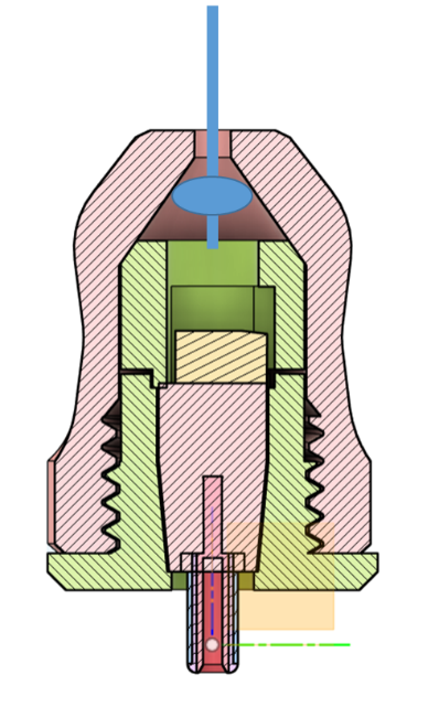
Place the Barrel Jack Plug electronic part inside the 3D printed housing and screw the housing to the faceplate (Figure 34).
Figure 34: Hammer Plug Assembly.
7. Wiring Assembly
You will need
Item
Quantity
Assemblies
Completed Tower
×1
Hit Box Assembly
×1
LED Assembly
×1
Electronic Components
×1
Hammers and Plugs
×1
Electronics
2 or 3-strand Wire (1.5 m minimum)
×3
3-strand Wire (1.5 m minimum)
×1
Male Barrel Jack Hammer Plugs
×3
Bootlace Ferrules, 22AWG
×1
Blade Terminals
×1
Female Barrel Jack Connector
×1
1000 µF Capacitor
×1
500 Ω Resistor
×1
Female 3-wire JST Connector
×1
Heat Shrink
×1
Raspberry Pi 4B
×1
Screw Terminal Header for Raspberry Pi
×1
12 V Step-Up/Step-Down Voltage Regulator
×1
Micro HDMI to HDMI Cable
×1
LED Power Supply
×1
Screen Power Supply
×1
Raspberry Pi Power Supply
×1
3D Printed Parts
Electronics Mounting Plate
×1
Tools
Bootlace Terminal Crimp
×1
Wire Crimper for Blade Terminals
×1
Size 0 Philips Head Screwdriver
×1
Size 00 Flathead Screwdriver
×1
3 mm × 1 mm Zip Ties
×1
Velcro Strips
×1
Steps
Referencing the Electronics Diagram in the electronics diagram, wire the Female Barrel jack plugs with 2 or 3-strand wire.
Cut each to length so it can be fed up through the Tower Wire Grommet and to the top of the Tower, where the Raspberry Pi will sit; approx. 1.5 m each.
Strip the wire ends, and attach a Bootlace terminal to each end, then attach to Barrel Jack screw terminals.
With wires attached, unscrew the plastic nut on the back of the Hammer Plug Panel Mounts, remove the side plate, and place the Female Barrel Jack Plug inside.
Replace the side plate, and tighten the plastic nut to trap the wired Barrel Jack.
Referencing the Electronics Diagram in the electronics diagram, wire the ‘Select’ Arcade button 3-strand wire.
Cut each to length so it can be fed up through the Tower Wire Grommet and to the top of the Tower, where the Raspberry Pi will sit; approx. 1.5 m.
Strip the wire ends, and attach a Blade terminal to each end, then attach to the Arcade Button wiring blades.
Referencing the Electronics Diagram in the electronics diagram, prepare a wiring harness for the LEDs:
Use a Female Barrel Jack connector (matching the LED Power Supply).
Place a 1000 µF capacitor across the +ve and -ve sides of the Barrel Jack
Cut a short length of wire each for the +ve and -ve connections for power. Terminate the ends with a Bootlace connector.
Strip a short section in the middle of each wire to splice in the JST wires.
Solder the Female JST +ve and -ve to these wires as a splice.
Wrap each splice in electrical tape or heat shrink.
Cut the Data JST wire, and solder a 500 Ω resistor in the middle, reattaching the Data wire with the resistor in the middle of the cut. Heat shrink or electrical tape the join to protect the resistor.
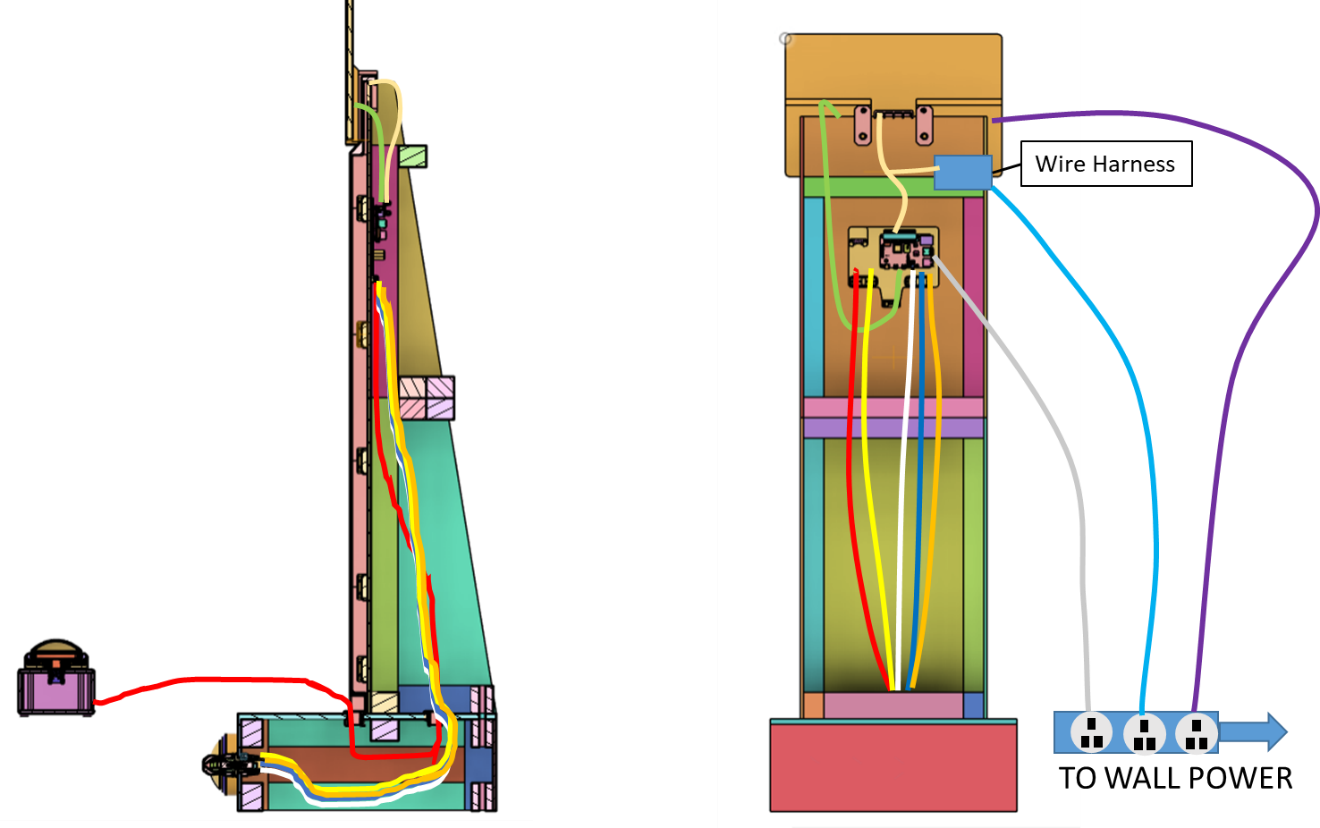
Route all cables according to the simplified wiring diagram in Figure 35.
Red = Hit Box 3-strand Wire
Yellow = Select Button 3-strand Wire
White, Dark Blue, Orange = Hammer Female Barrel Jack Plugs
Green = Screen HDMI
Beige = LED Data and Power
Light Blue = LED Power Supply
Purple = Screen Power Supply
Grey = Raspberry Pi Power Supply
Figure 35: Simplified Wiring Diagram of the Electron Ejector.
Attach the Screw Terminal Header to the Raspberry Pi.
Screw the Raspberry Pi to the Electronics Mounting Plate.
Screw the 12 V Voltage Regulator to the Electronics Mounting Plate, and attach the cover with zip ties.
Attach the Electronics Mounting Plate to the back of the Tower with Velcro Strips.
Zip tie the Arcade Button and Hammer Plug wires to the Electronics Mounting plate on the printed pedestals.
Terminate all wire ends to be plugged into Raspberry Pi screw terminal header with Bootlace ferrules.
Perform the detailed wiring to the Raspberry Pi and the 12 V Step-Up/Step-Down Regulator per the Electronics Diagram in the electronics diagram, but ensure NO POWER is plugged in.
Double-check the wiring, then plug into power and turn on the Raspberry Pi.
Attach a keyboard and mouse to complete the setup.
Download and run the Electron Ejector code from GitHub.
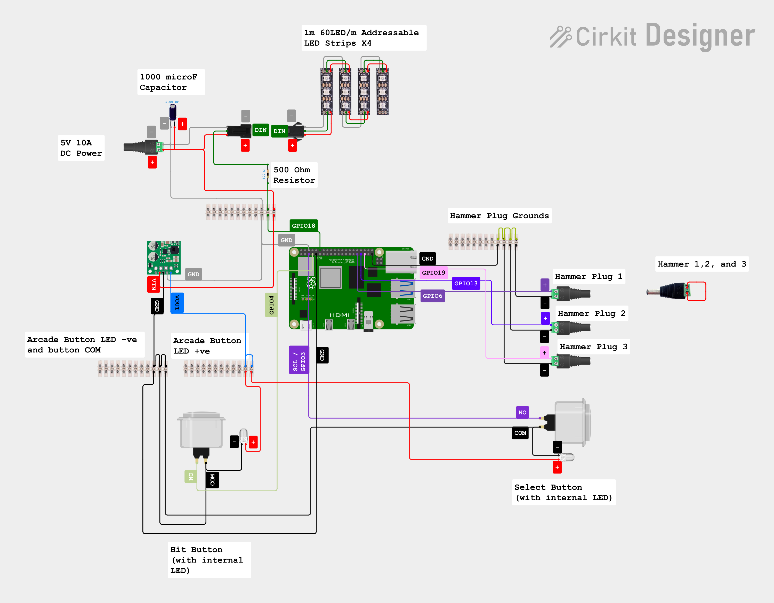
Electronics diagram
Full electronics diagram for wiring the Electron Ejector components.